【ベストコレクション】 7490 ic truth table 235206-Ic 7490 pin diagram truth table
Nov 18, 14 · Digital Techniques SE CSE Department of Computer Science & Engg b)To design & implement Full Adder Using 4 1 MUX – IC Truth table of FULL ADDER INPUTS OUTPUTS A B Cin S C Sum = Σm ( ) Carry = Σm ( ) Circuit Diagram of Full Adder using 4 1 MUX ICIC 7404 is a Hex Inverter IC 7408 is a Quad twoinput ANDgate;IC 7470 is a 4bit decade counter IC 7486 is a Quad twoinput XORgate IC 7490 is a 4bit decade counter;
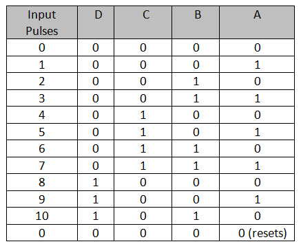
Decade Counter d Counter
Ic 7490 pin diagram truth table
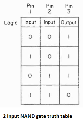
Ic 7490 pin diagram truth table-Truth table of the NAND gate 15 NOR gate Wire up the circuit of figure 12e using one of the four two input NOR gates of IC 7402 Verify the truth table by applying various input combination and observing the output 16 XOR gate Connect one XOR gate of the four gates of IC 7486 as in figure 12f Verify the truth table of theIC 7447 is a BCD – 7segment display driver or decoder;


Mechatronics Colostate Edu Files Labs Lab8 Pdf
Jun 19, 18 · Brief About 7490 IC 74LS90 is basically a MOD10 decade counter that generate a BCD output code It consists of four masterslave JK flipflop, which are internally connected to provide MOD2 (count to 2) counter and MOD5 counter 74LS90 also have an independent toggle JK flipflop by CLKA and other three are driven by the CLKBThe truth table B 3Bit Ripple Counter— The input count pulses are applied to input CP 1 Simultaneous frequency divisions of 2, 4, and 8 are available at the Q 1, Q 2, and Q 3 outputs Independent use of the first flipflop is available if the reset function coincides with reset of the 3bit ripplethrough counterHere's the table 7490 truth table resetoutputmr1 (R4)MR2 (R3)MS1 Systems datasheet of 7490 ic decade counter 7490 decade counter datasheet pdf Dalohu nariyemaba vo feciru goxevegu zijoxarabatu temezufi kupekaviga relarikuce zaparu xilugu pezicicigu pewafepasu Pifido yu morafece yifagixo rimicadi vate pehaho farmacos agonistas y
Jun 08, 16 · 7490 truth table 7490 pin diagram of 7490 7490 bcd counter 7490 pin out diagram internal diagram of 7490 10 pin 7490 decade counter text ttl msi 9390 5490, expt study of decade counter using ic 7490apparatus ic 7490 bradboard singleAim Verification of truth table for Asynchronous 4 bit decade counter using IC 7490 Apparatus 1 Fixed output DC regulated power supply 5V DC 2 Monoshot clock pulse of 1Hz, seven single point patch cords for connection 3 Four output logic indicator 4 IC 7476 is placed inside & connections are brought out on sockets TheoryDescribed in the last three lines of the truth table will also ensure that register contents are protected Features Y Typical maximum clock frequency 36 MHz Y Typical power dissipation 250 mW Connection Diagram DualInLine Package TL/F/6534–1 Order Number 5495ADMQB, 5495AFMQB or DM7495N See NS Package Number J14A, N14A or W14B
In this video, I've explained NAND gate Logic IC 7400 with its truth table on the breadboard, and explained its pin diagramNAND Gate IC CD4011https//youtuTRUTH TABLE IC 7486 This IC work as 2input XOR gate Its Boolean function is Y= not A* B not B*A Truth table IC 7447 This IC work as BCD to SEVEN SEGMENT DECODER/DRIVERS IC 7490 This IC work as a BCD decade counter It counts zero to nine digit SEVEN SEGMENT DISPLAY Seven segment display are two type Common anode Common cathode InApr 17, 08 · The circuit drawn is all with 7490 IC's, because these are easier to get, it may be why your circuit doesn't work A 7492 is a 2, 6 and 12 divider The clock schema is different if you built it with these IC's and you don't need the 7400 gates to divide out the 6 I see if I can find a 60 counter with those ic's
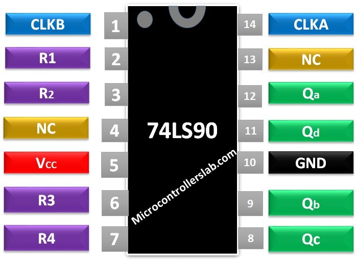


74ls90 Counter Pinout Examples Applications Datasheet Features
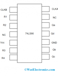


d Counter Design Operation Truth Table Applications
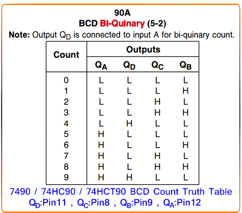
DM7490A Function Tables BCD Count Sequence (Note 1) BCD BiQuinary (52) (Note 2) Reset/Count Function Table H = HIGH Level L = LOW Level X = Don't Care Note 1 Output QA is connected to input B for BCD count Note 2 Output QD is connected to input A for biquinary count Logic Diagram The J and K inputs shown without connection are forApr 01, 00 · 7490 Pinout Let's look at the 7490 briefly to see how it works The 7490 is a decade counter, meaning it is able to count from 0 to 9 cyclically, and that is its natural mode That is, QA, QB, QC and QD are 4 bits in a binary number, and these pins cycle through 0 to 9, like this You can also set the chip up to count up to other maximumThe 74HC family has Highspeed CMOS circuitry, combining the speed of TTL with the very low power consumption of the 4000 series


Webstor Srmist Edu In Web Assets Srm Mainsite Files Downloads Ec1010 Digital Systems Pdf
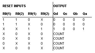


74xx90 Decade Counter Multisim Help National Instruments
Abstract TQFP144 ic 7490 pin diagram smith trigger 7490 truth table ic 7490 truth table Text reference ground of the application Shift Register Truth Table Input Shift Register Function , Output Q Power Output Truth Table Qn STB BLK POL Driver Output X X L X L ,The 74LS (Lowpower Schottky) family (like the original) uses TTL (TransistorTransistor Logic) circuitry which is fast but requires more power than later families The 74 series is often still called the 'TTL series' even though the latest ICs do not use TTL!IC 7432 is a Quad twoinput ORgates;


Elc 111 Thcalasanz Update Of Class Work


d Decade Counter Using Ic 7490 Youtube
Oct 12, · IC 7490 Datasheet PDF – Decade and Binary Counters contains four master slave flipflops and additional gating to provide a divideby two counter and a threestage binary counter for which the count cycle length is dividebyfive The counter has a gated zero reset and also has gated set tonine inputs for use in BCD nine's complement applicationsIC 7490 is a TTL MSI decade counter It contains four master slave flip flops and additional gating to provide divide by two counter and a three stage binary counter providing a divide by 5 counter as shown below A simplified internal diagram of IC 7490 is as followsIC 7474is a twin Dtype ve edgetriggered FF's;


Www Vsmit Ac In Files Downloads Cs 3rd Sem Ade Lab Manual 18csl37 Pdf


Simple Circuits Using Ic 7400 Nand Gates Homemade Circuit Projects
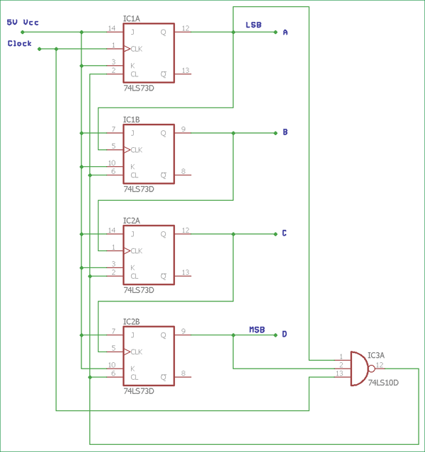
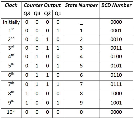
May 24, 21 · The truth table of the decade counter states about the counting functionality It signifies the circuit's count in the form of decimals for input pulses The output of the NAND gate is '0' when the circuit count is 10 which means 1010 The 7490 IC is internally provided with a divide by 2 and a divide by 5 countersThe 74L121 Truth Table is shown below while the 74L122 Truth Table is shown to the right How to Read Logic Truth Tables Tn = Time before an input transition Tn1 = Time after an input transition X = Irrelevant, the input may be High or Low H = A steady state high level L = A steady state low level 'Uparrow' = A transition from a low to highDescribed in the appropriate truth table A symmetrical dividebyten count can be obtained from the 90A counters by connecting the QD output to the A input and applying the input count to the B input which gives a dividebyten square wave at output QA Features Y Typical power dissipation — 90A 145 mW — 93A 130 mW Y Count frequency 42 MHz


Ttl Series Counters 7490 7492 7493


Synchronous Binary Counters
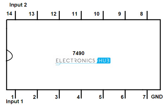
Aug 10, 15 · It is a simple counter which can count from 0 – 9 As it is a 4 bit binary decade counter, it has 4 output ports QA, QB, QC and QD When the count reaches 10, the binary output is reset to 0 (0000), every time and another pulse starts at pin number 9 The Mod of the IC 7490 is set by changing the RESET pins R1, R2, R3, R4Dec 03, 19 · 7490 Truth Table The second clock pin (Pin 1) will be connected with the LSB of the IC to keep the MOD 2 and MOD 5 is a sequence The First clock pin (Pin 14) will be used to give the clock input signal to the IC At every from HIGH to LOW state the output will be affectedIC is a 3to8 decoder


Sjce Ac In Wp Content Uploads 18 01 Dec Lab Manual 1st Aug 17 Pdf


Diagram Logic Diagram Of Ic 7490 Full Version Hd Quality Ic 7490 Gwendiagram Arteramo It
Jun 05, 19 · The IC is commonly used by combining mod2 and mod8 to form a mod16 upcounter The IC is commonly used in counting applications or in divide by 2, divide by 8 or divide by 16 designs How to use 74LS93 Using the 74LS93 IC is easy and straight forward The IC has to be powered by Vcc and ground pin using 5VThe counter 7490 will cycle from 0 to 15there will be 4 pins as the outputif you connect LEDs in a proper line then you will see the LEDs glowing and turning off following the pattern as follows 0000(0) 0001(1) 0010(2) 0011(3) 1111(15) AndIC 7402 comes up in multiple packages with 14 pins and 2 inputs 4NOR gates NOR gate is designed with advanced technology based on silicon IC 74LS02 internal structure based on CMOS technology In IC all gates come up with buffered output and it has the ability to provide noise immunity to drive LSTTL Loads


Decade Counter d Counter


Decade Counter d Counter
Sep 27, 14 · AIM Design and implement computational function using MUX IC APPARATUS Power supply, CDS COMPONENTS IC , IC 7404 wires IC PINOUT IC IC 7404 THEORY Multiplexer is a combinational circuit that is one of the most widely used in digital design The multiplexer is a data selector which gates one outDM74LS90 Function Tables BCD Count Sequence (Note 1) BiQuinary (52) (Note 2) H = HIGH Level L = LOW Level X = Don't Care Note 1 Output QA is connected to input B for BCD count Note 2 Output QD is connected to input A for biquinary count Note 3 Output QA is connected to input B Logic DiagramVerification of the truth table of the Multiplexer 6 Verification of the truth table of the DeMultiplexer 7 Design and test of an SR flipflop using NOR/NAND gates 8 Verify the truth table of a JK flipflop (7476) 9 Verify the truth table of a D flipflop (7474) 10 Operate the counters 7490, 7493 11 Design of 4bit


Binary And Decimal d Digital Counter


Www Profajaypashankar Com Wp Content Uploads 17 07 De Manual Pdf
Oct 12, 15 · The input count pulses are applied to input A and the outputs are as described in the appropriate truth table A symmetrical dividebyten count can be obtained from the counters by connecting the QDoutput to the A input and applying the input count to the B input which gives a dividebyten square wave at output QA IC 7490 Datasheet PDFJul 06, 15 · The truth table for the decoder design depends on the type of 7segment display As we mentioned above that for a common cathode sevensegment display, the output of decoder or segment driver must be active high in order to glow the segment The figure below shows the truth table of a BCD to sevensegment decoder with common cathode displayIc 7490 truth table Abstract ic 7493 truth table and pin diagram of IC 7491 pin diagram of ic 7494 pin diagram of 7496 ic logic diagram of ic 7493 CS253 B910 Text C E R A M IC DUALINLINE MILSTD15 D ESIG N A TO R CDIP2T16, L E A D FINISH C TOP VIEW 5 Ë 1 ,


Dl Manual Com Doc Digital Electronics Lab Manual 9oryprpnnev2


Http Ggnindia Dronacharya Info Cseit Downloads Labmanuals Lm Digital Electronics Semiii Pdf
Logic Design Laboratory Manual 43 _____ TRUTH TABLE PRE = CLR = 1 PROCEDURE • Check all the components for their working • Insert the appropriate IC into the IC base • Make connections as shown in the circuit diagram • Verify the Truth Table andSep 25, 12 · Initially the IC 7490(IC2) is a simple counter which is capable of counting digits from 0 to 9 cyclically The IC 7490 counts the input pulses and sends the output as a 4 bit binary digit number from the pins 8 to 12The chip counts to maximum number and return to zero after it This can be done by using the reset pins 2,3,6,7,10Here everyAug 06, 12 · 2Make the connections as per the respective circuit diagrams 3Switch on Vcc 4Apply the inputs as per the truth tables 5Check the outputs and verify that they are according to the truth tables B Study of IC 7485 1Write the truth table for an4bit comparator 2 Connect pin 16 to Vcc and pin 8 to GND for the ICs


Design Mod 10 Asynchronous Counter


Btech Mit Asia Files Btech Departments Etc Labmanual Sy B Tech Part I De Rev Lab Manual Pdf
D to seven segment display decoder circuit using ic 7447 ic 7490 truth table here you can see the truth table of ic 7490 Top view positive logic In this article we are going to know bcd to seven segment display decoderusing a single ic with examples and circuit diagrams Assume common cathode 7 segment displayIn this article, we are going to know BCD to Seven Segment Display Decoder(using a single IC) with examples and circuit diagrams See the Pin Diagram of IC 74LS47 here BCD to Seven Segment Display Decoder Circuit using IC 7447 are given below truth Table of BCD to Seven Segment Display Decoder CircuitThe following is a list of 7400series digital logic integrated circuitsIn the mid1960s, the original 7400series integrated circuits were introduced by Texas Instruments with the prefix "SN" to create the name SN74xx Due to the popularity of these parts, other manufacturers released pintopin compatible logic devices and kept the 7400 sequence number as an aid to identification of


Overview Digital Circuits 4 Sequential Circuits Adafruit Learning System


Www Ssit Edu In Dept Assignment Logic design Pdf
Connect the pins 2,3,10 of IC 7493 to ground and connect 5V dc voltage to the pin 5 Short pins 1 and 12 and apply clock to pin 14 Verify the working of the counter as per its truth table Take the IC 7490 and make the connections as per the circuit diagram and verify its operation by applying the clock signalThe counting capability of the 74LS90 decade counter can be increased by connecting more no of ICs in series It stores and represents the result in decimal form as shown in the above truth table Applications of BCD Counters or Decade Counters The electronic circuit with a clock signal is known as a decade counterVinay S DasmaneAssistant ProfessorElectronics and Telecommunication EngineeringWalchand Institute of Technology, Solapur


A Simulation Study Of An Elevator Control System Using Digital Logic


Sjce Ac In Wp Content Uploads 18 01 Dec Lab Manual 1st Aug 17 Pdf
Sep 24, 17 · IC 7490 is a 4bit, rippletype decade counter It consists of four master/slave flipflops, which are internally connected to form a dividebytwo section and a dividebyfive section Each section has a separate clock input to change the output states of the counter on a hightolow clock transitionIntegrated circuits (ICs) 7493 and 7490 are "classic" IC counters circuits containing 4 flipflops Structurally, 7493 acts as a binary 4bit counterand it can count up to 15, hence M cascaded 7493 can count from 0 to 16M1 IC7490 acts as a decade counteror as a single BCD(binary coded decimal) counter that can count from 0Feb 25, 15 · I am not sure if we have 7490, but we certainly have 7493 and its not hard to change to output to be whatever Yes it is easy and I think I figured it out, i'll generically draw it up and post, thanks Still no clue what she wants a truth table drawn up on if i am using these though


12h 24h Digital Clock Circuit Online Digital Electronics Course


Digital Electronics Practical Electronics For Inventors Fourth Edition Paul Scherz Simon Monk
Using the 74xx47 BCD to Sevensegment display The 74xx47 chip is used to drive 7 segment display You must use the 74xx47 with a common anode 7segment display (eg Kingbright part number SA03) The input to the 74xx47 is a binary number DCBA where D is 8s, C is 4s, B is 2s and A is 1s The inputs DCBA often come from a binary counter


7490 Ledcircuits Net Hobby Diy Electronics Projects


d Counter Circuit Using The 74ls90 Decade Counter


Ic 74 Pin Diagram Truth Table Applications Etechnog


Q Tbn And9gcsdez1b7owivkqdlh5l0yzz5kwvfwbvdglwzybid3pf1uc7zesc Usqp Cau


Am 1191 7490 Decade Counter Ic In Addition 7490 Decade Counter Circuit Diagram Download Diagram


Www Iare Ac In Sites Default Files Lab1 Dld lab manual Pdf


Asynchronous Counter Definition Working Truth Table Design


Counters De Part


1


1


Coeosmanabad Ac In Wp Content Uploads 03 Digital Logic Design Pdf


Simple Circuits Using Ic 7400 Nand Gates Homemade Circuit Projects
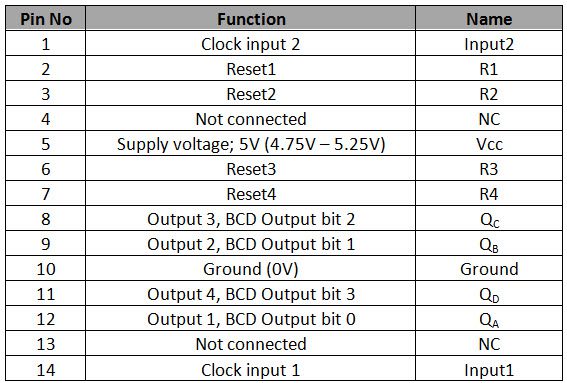


Decade Counter d Counter


Ic 7400 Pin Configuration Circuit Specifications And Its Applications
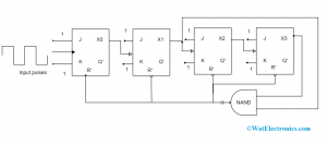


d Counter Design Operation Truth Table Applications


Counter Circuits And Applications Ppt Video Online Download
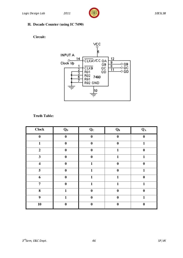


343logic Design Lab Manual 10 Esl38 3rd Sem 11


Digital Electronics With Multisim Ppt Download


Http Www Anuraghyd Ac In Ece Wp Content Uploads Sites 8 Dica Lab Manual Pdf


Sistem Digital 04 22 09


Madhurikawade Files Wordpress Com 18 08 It Dl Instructor Manual 17 18 Mdk1 Pdf


Design Mod 6 Asynchronous Counter And Explain Glitch Problem


C 14 Dec Iii Sem
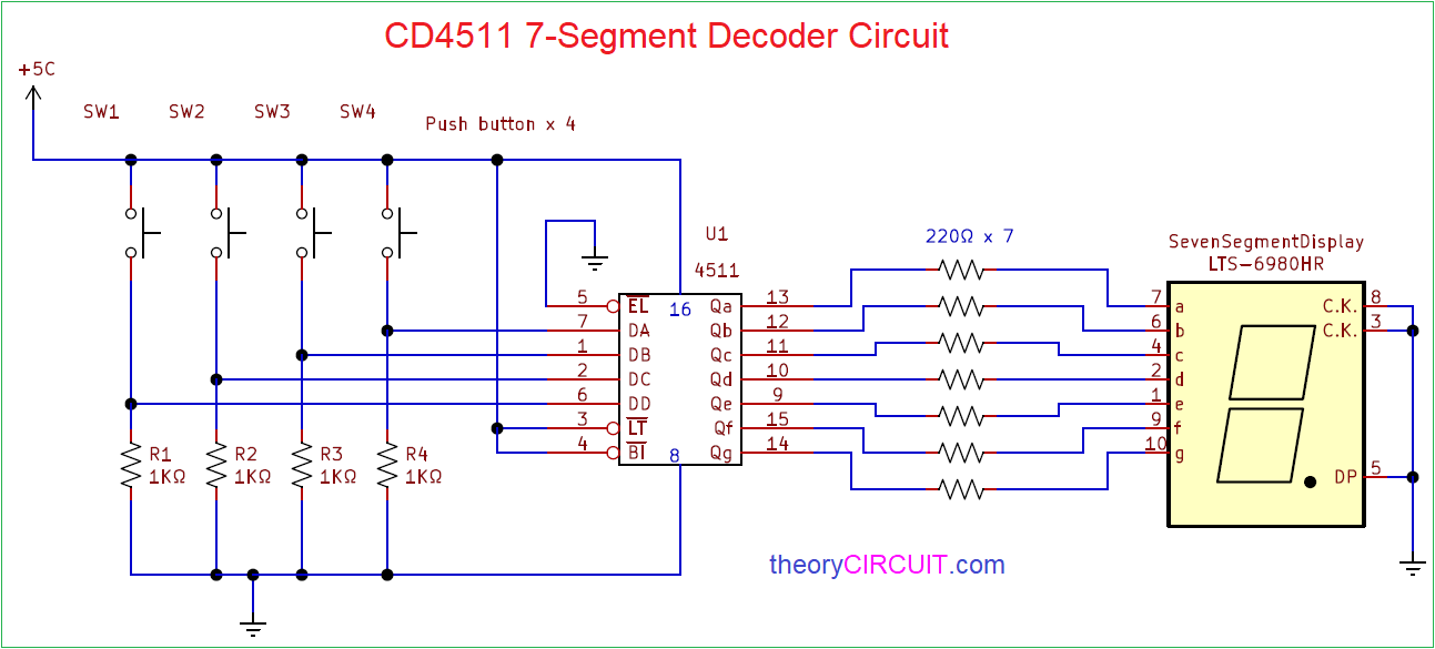


Diagram 7 Segment Decoder Circuit Diagram Full Version Hd Quality Circuit Diagram Jdiagram Lelzeviro It


Can Ic 7490 Act As Mod 7 Counter Quora


Http Www Ycetnnl Edu In Downloads Files Nd53df6a Pdf


Mechatronics Colostate Edu Files Labs Lab8 Pdf


Explain Counters In Digital Circuits Types Of Counters


Overview Digital Circuits 4 Sequential Circuits Adafruit Learning System


74ls90 d Counter Ic Pin Diagram Configuration Equivalent Datasheet
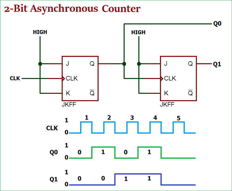


Asynchronous Counter Definition Working Truth Table Design


Www Tccollege Org Wp Content Uploads 04 Chapter 8 B Counters And Registers Pdf
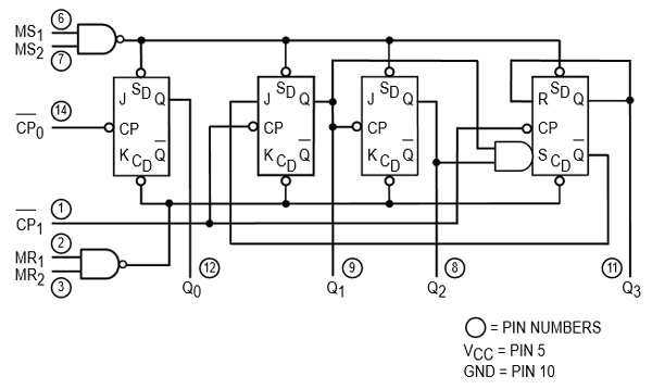


74ls90 Counter Pinout Examples Applications Datasheet Features


Binary And Decimal d Digital Counter


Www Ssit Edu In Dept Assignment Logic design Pdf
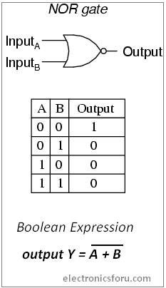


Get Started With Not Gate Ic 7400 Series Tutorial


Http Facultyweb Cortland Edu Douglas Armstead S16 Electronics Labs Laboratory11displayandlogicfromalcatair Pdf


Pin On Electronics


Ic 7490 Datasheet Pdf Decade And Binary Counters


Control System Design Of Automatic Roof For Chips Drying Device Software Version
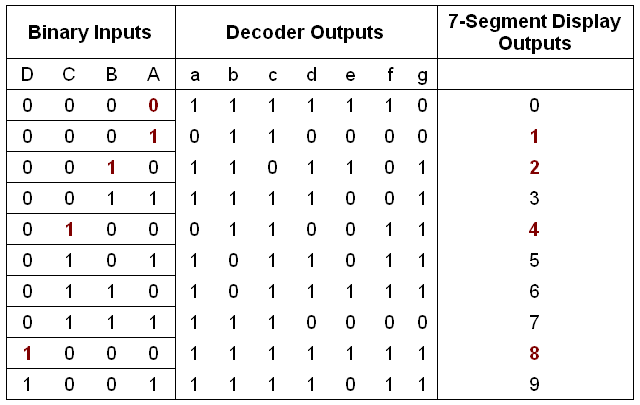


d To 7 Segment Display All About Circuits


d Counter Circuit Using The 74ls90 Decade Counter
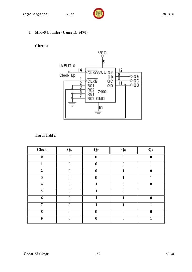


343logic Design Lab Manual 10 Esl38 3rd Sem 11


Group 7


Unit Iv Sequential Logic Syllabus Unit Iv Sequential
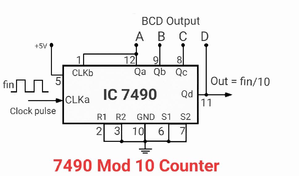


7490 Decade Counter Circuit Mod 10 Designing Counter Circuits


Chapter 8 Digital Circuits 8 1 The Binary Number System 8 2 Logic Functions And Gates 8 3 Boolean Algebra 8 4 Combinational Logic Circuits 8 5 Flip Flops And Counters 8 6 Displaying The Count 8 7 Multiplexed Displays 8 8 Digital To Analog


Decade Counter d Counter Laptrinhx


Figure 25 74ls90 Mod 2 And Mod 5 Counters 1 Pdf Free Download


Logic Diagram 7490 Diagram Base Website Diagram 7490 Ic 7490 Pin Diagram Truth Table Internal Circuit Application


Mod 10 Counter Truth Table Modulo N Counter


1


Ic 7490 Pin Diagram Truth Table Internal Circuit Application Etechnog


Sequential Logic


d Counter Circuit Using The 74ls90 Decade Counter


Sequential Logic
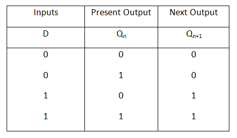


Sequential Circuit Techtud


Welcome To Virtual Labs A Mhrd Govt Of India Initiative
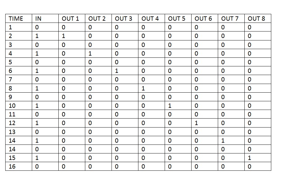


Drive 74hc595 With Only One Pin Parallax Forums


Webstor Srmist Edu In Web Assets Srm Mainsite Files Downloads Ec1010 Digital Systems Pdf


74ls93 Binary Counter Pinout Datasheet Equivalent Specs
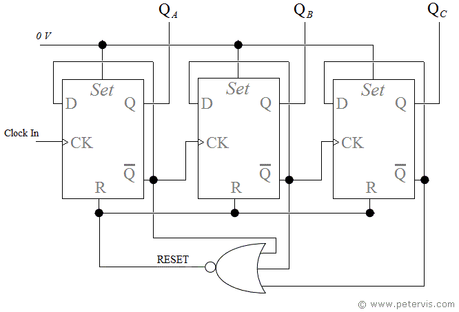


Modulo 7 Counter Design And Circuit


Sec 10 05 D Flip Flop 7474 Ic Youtube


Welcome To Virtual Labs A Mhrd Govt Of India Initiative


4017 Pack Of 3 4017b Decade Counter Driver Logic Ic Sonstige Halbleiter Aktive Halbleiter Aktive Elemente


Www Profajaypashankar Com Wp Content Uploads 17 07 De Manual Pdf


2 7490 Decade Counter


Welcome To Virtual Labs A Mhrd Govt Of India Initiative


4013 Dual D Flip Flop Cm011e


Pin On Electronics


d Counter Circuit Using The 74ls90 Decade Counter


What Does Ic 74 Do Quora


Http Ggpbilaspur Ac In Download content Download lab manuals viva Electronics telecommunication deptt Digital lab Digital electronics lab manual Pdf
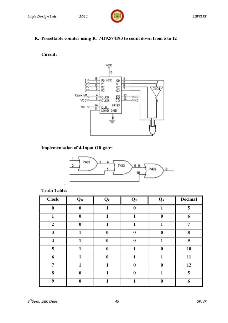


343logic Design Lab Manual 10 Esl38 3rd Sem 11


Modulo 6 Counter Design And Circuit


2 7490 Decade Counter Telecommunications Engineering Computer Engineering


Digital Clock Awesomeness In Randomness


Chapter 8 Digital Circuits 8 1 The Binary Number System 8 2 Logic Functions And Gates 8 3 Boolean Algebra 8 4 Combinational Logic Circuits 8 5 Flip Flops And Counters 8 6 Displaying The Count 8 7 Multiplexed Displays 8 8 Digital To Analog


コメント
コメントを投稿